Handwheel Dial and Micrometer Scale Settings
Is Fully Open the Maximum Calibrated position?
During my early years working as a TBT I questioned the micrometer scale settings on some calibrated balancing valves, “What is fully open?” While this may be easily understood by experienced TBT’s and TBE’s, it is often misunderstood by beginning technicians, as well as by engineers and contractors. It is important for mentors to pass this information on and to be able to articulate it to those outside the TAB field.
Let’s begin with some simple definitions. Zero is typically closed and will be very close to the zero reading on the micrometer scale. The Calibrated Maximum is the point where the micrometer scale ends and the limit of the manufacturer’s calibration. Fully open may be the same as the Calibrated Maximum, or it could be past the Calibrated Maximum. We will describe the procedures and differences below.
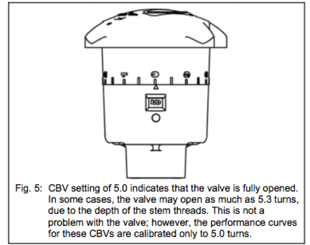
First, closing or “zeroing” the valve can be used to find the Calibrated Maximum position on a micrometer scale handwheel. The valve is generally considered “zeroed” when fully closed hand tight. The “0” on the micrometer scale should typically be within one half of 1/10th of a turn of the pointer indicator when the valve is closed hand tight. Do not use a wrench on the valve, it should be opened and closed, hand tighten only. Once the closed or “zeroed” position is found, the valve can be opened to the Calibrated Maximum position using the numerical scale on the valve. In most cases it will be the highest number listed on the handwheel dial. For example, if the handwheel dial is marked 0-5 and the micrometer scale is marked 0-9, the Maximum Calibrated position will be 5 on the handwheel dial and 0 on the micrometer scale. In some cases it is possible to move the valve past the Calibrated Maximum position. This will usually decrease the pressure drop, leading to an incorrect conclusion that the flow has decreased. This should be avoided by stopping on the Calibrated Maximum position found by using the “zeroing” method. While opening the valve past the Calibrated Maximum on the scale may actually increase flow, it is impossible to read it since the valve is now adjusted outside of the manufacturer’s calibrated range.
Calibrated balancing valves may be installed with the memory stops pre-set from the manufacturer or supplier. This means you cannot open the valve beyond that point, and it stops before the Calibrated Maximum position. Determine the flow rate at the pre-set position and if additional flow is needed, opening the calibrated balancing valve further will be required. Be aware that many manufacturer memory stops are hidden. Manufacturers often locate memory stops within the handwheel mechanism and in some cases you need to remove the top of the handwheel for access. The handwheel as a whole is not designed to be removed. Most memory stops can be adjusted out with an Allen wrench or a small screwdriver to allow for more flow. It is good practice to set the memory stops on balancing valves when available. This action may help validate the Test and Balance Report if problems later arise with the hydronic system.
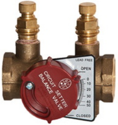
Another brand specific question often raised is which part of the red plastic knob or indicator plate should be aligned with its numerical degree set point on a B&G Circuit Setter Plus valve. The manufacturer clarification is, “…set the hairline over the degree of closure as indicated by the part of the red plastic knob or indicator plate PARALLEL to the degree of closure noted on the calibration plate.”
 Remember, it is important to know where the calibrated scale begins and ends for accurate flow readings. Refer to manufacturer submittals or technical literature on the particular calibrated balance valve. If this does not provide adequate direction, contact the manufacturer for additional clarification. Most are willing to answer specific questions and provide technical support related to their products.